External Display on ESP32: Representing GIF on OLED
Hi guys it’s Ananta again, how are you? I hope you’re feeling well, the weather here in my area is getting kinda weird, it could be sunny, humid, and warm in the morning and then stormy and cold a few hours later. I think I caught a cold this morning on my way back home from my grandma’s riding a speedboat, the wind was kinda crazy tho.
Back again with my ESP32 module for this week. As you might have seen on the title, I will be using an external display for this module. I’ve bought an OLED (organic light-emitting diode) a few weeks ago, so I will be using it for this module’s experiment.
Maybe you’ve heard about LED and OLED, and interested in knowing the differences. OLEDs’ panels are able to display certain colors when they’re electrified without any need of backlight, while LEDs are containing pixels (coloured dots that make colors in TV display) yet they could not work on their own, they need some source of lights from the background to make the pixels visible called the backlight. (Disclaimer: this is a simplified explanation, for detailed explanation you can check this article).


However I’ll use a monochrome OLED for this module, so all we can see from the display are white lights and black default background. I will try to represent a GIF image on OLED, GIF is a moving image consisting of frames. How do I display a moving image on an external display? Let’s get started!
All we gonna need for this module’s experiments are:

- ESP32 and breadboard(optional)
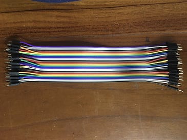
- Dupont wires
- OLED 128x64 px Display
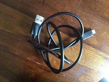
- MicroUSB Cable
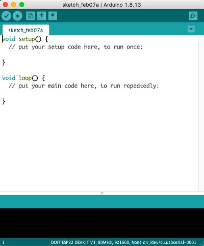
- PC with Arduino IDE installed
(click the name for images)
The next thing we got to prepare is the circuit, as usual i’m using Fritzing software to draw the circuit diagram, looking like this:


As usual we need to connect the ESP32’s ground to OLED’s ground, the ESP32’s voltage source to the OLED’s voltage receiver, and here I picked GPIO21 to be connected to SDA (data line), and GPIO22 to be connected to SCL (clock line). There are some preparations we need to do before starting to write the code for this module:
Download the SSD1306 Library, this is the general library for OLED SSD1306 monochrome 128x64 px display. Go to Tools > Manage Libraries, type “ssd1306”


Usually the software will suggest us to download another library through a pop-up, Adafruit GFX Library. But in case no pop-up appeared, we could manually find the library in the library manager by typing “GFX”

A. EXAMPLE CODE
With all prerequisite library installed, we are ready to test whether the circuit matches the code so it can display something on the OLED. To find out, we can use the example code from Adafruit. Go to File> Examples> Adafruit SSD1306> ssd1306_128x64_i2c then you will see an example code. You can see the code here:
I did some modification though to the code, first I defined the OLED reset as -1 instead of 4 because I have no reset button on my ESP32. The other one is somewhat weird, took me some times to figure out that i need to change the screen address to 0x3C (which is the address of 128x32 OLED) instead of keeping the address at 0x3D (address of 128x64 OLED).

Well I think there would be no further problem after as long as the code works on the OLED. All you gotta do is click the compile button on top of the IDE, wait for some seconds, and Ta-Da, something will appear on your OLED. This is more or less what it’ll look like
B. DRAWING SHAPES
I’ll show you how to draw some shapes on the OLED. We could use the procedure display.drawrect and fill the parameters with x-coordinate, y-coordinate, width, height, and color in order. I’ll try this code to make a rectangle (more of a square, to be honest).
display.drawRect(40, 20, 40, 40, WHITE);You can fill the rectangle too by switching the drawRect procedure into fillRect with the same parameters.
display.fillRect(40, 20, 40, 40, WHITE);I’ll try to draw a circle too using drawCircle procedure, yet the parameters are quite different. The parameters are drawCircle(x-coordinate, y-coordinate, radius, color). I’ll try something looks like this:
display.drawCircle(64 ,32 ,15 ,WHITE);You can find the whole code here, and the OLED would show something like this:


C. REPRESENTING GIF
My favorite part! We can represent our own GIF (Graphics Interchange Format) on the OLED. I chose to represent a GIF because it’s the nearest and simplest we could get from representing a video! Here i’ll use a 5-frame GIF of a girl and bear breakdancing I’ve shown u earlier above by Dami Lee.
First thing first, we should split gif frames into JPG / JPEG images. Because I’m using a 5-frame GIF, there would be 5 JPEG produced

The next step is converting the pictures into bitmap array. Thank you to this tutorial I could easily convert the JPEG into bitmap array. The tutorial is really good and adequate. The tutorial really directed me to convert JPG to a bitmap array, along with the program so that we no longer need to download any software from third parties. Noteworthy, there are some setting we need to adjust on the program from the default setting:
- Change the canvas size from 720x360 to 128x64
- Invert image color (optional, the background would be dark if performed)
- Change the scaling to “scale to fit, keep proportion”
- Change output format to “Arduino code”
- You can also change the identifier to the name you desired for the array
All set, all you gotta do now is generating the code!!!


Repeat for all the frames. Don’t forget to name all of the bitmap arrays differently, here I’m using bd1, bd2, bd3, bd4, bd5. You can see the whole code here :
I’ll explain about the code for a bit, The bitmap array will define the color OLED should provide, it will show 5 different bitmap arrays to represent 5 frames, the higher the bitmap character (0xFF), the brighter the color / white, while the lower character (0x00) indicates a dark color or the diode is not electrified. Oh and don’t forget to insert the library driver too!
#include <Wire.h>
#include <Adafruit_GFX.h>
#include <Adafruit_SSD1306.h>#define SCREEN_WIDTH 128
#define SCREEN_HEIGHT 64Adafruit_SSD1306 display(SCREEN_WIDTH, SCREEN_HEIGHT, &Wire, -1);const unsigned char bd1 [] PROGMEM;
const unsigned char bd2 [] PROGMEM;
const unsigned char bd3 [] PROGMEM;
const unsigned char bd4 [] PROGMEM;
const unsigned char bd5 [] PROGMEM;
As usual, the setup procedure will determine the data transfer rate in bits per second. We are using 115200 bits/second here. If the ESP32 doesn’t detect any SSD1306 on the system, It’ll give us an error message. But if the opposite happens, then we can move on to the loop procedure.
void setup() {
  Serial.begin(115200);

  if(!display.begin(SSD1306_SWITCHCAPVCC, 0x3C)) {
    Serial.println(F("SSD1306 allocation failed"));
    for(;;);
  }
  delay(2000); // Pause for 2 seconds
}
Before displaying each frame, it would be better if we delete the previous frame first with the clearDisplay procedure. Then, we can represent the bitmap arrays we prepared earlier with the drawBitmap procedure and display it with the display procedure. An image will last for 500ms before switching to the next image, meaning the frame rate is 2 fps (frames per second). The procedure will repeat to the first image if all images have been displayed.
void loop() {
  // Clear the buffer.
  display.clearDisplay();

  // Draw bitmap on the screen
  display.drawBitmap(0, 0, bd1, 128, 64, 1);
  display.display();
  delay(500);// Clear the buffer.
  display.clearDisplay();

  // Draw bitmap on the screen
  display.drawBitmap(0, 0, bd2, 128, 64, 1);
  display.display();
  delay(500);// Clear the buffer.
  display.clearDisplay();

  // Draw bitmap on the screen
  display.drawBitmap(0, 0, bd3, 128, 64, 1);
  display.display();
  delay(500);

    // Clear the buffer.
  display.clearDisplay();

  // Draw bitmap on the screen
  display.drawBitmap(0, 0, bd4, 128, 64, 1);
  display.display();
  delay(500);// Clear the buffer.
  display.clearDisplay();

  // Draw bitmap on the screen
  display.drawBitmap(0, 0, bd5, 128, 64, 1);
  display.display();
  delay(500);

}
All we gotta do when the code’s ready is compiling. Compile the code by clicking the right arrow button on the top of the IDE and wait for some seconds. This is the demonstration guys! Sorry for the background music 😂
Analysis
Well there are some points I learned through this module.
- We need to proof-read the codes we want to perform,In my first experiment I wanted to display something on OLED and it didn’t work because the code I ran the first time assumed that my microcontroller had a reset button so I needed to adjust the code first so that it worked as desired.
- Do not forget to use clearDisplay procedure before and display procedure after every drawing argument. If you don’t type the clearDisplay before displaying something, both layers will be displayed on OLED which doesn’t match the plan and could confuse you. You need to type display.display(); after every drawing arguments so that the resulting image can be displayed on OLED.
- The GIF experiment shows how videos are made from multiple images that are displayed and switched quickly. In order to get smoother GIF transitions we need more frames, and most videos now have a frame rate of 60fps, so much better than our experiment at the moment.
I think that’s all for this week guys! Thank you for reading and I wish you all a happy sunday! Ciao.
Materials quoted from
https://randomnerdtutorials.com/esp32-ssd1306-oled-display-arduino-ide/ https://diyusthad.com/2019/02/display-images-in-oled-display.html https://diyusthad.com/image2cpp